2.3.25 IPC-TM-650 Ionic Cleanliness Testing
This paper describes the test used to determine total ionic content extracted from the surface of printed circuit board for the purposes of process control. The manual method of beakers and flasks is first discussed, followed by an examination of an automated system using the “static” method of ionic extraction and finally the “dynamic” method of ionic contamination.
IPC-TM-650 TEST METHODS MANUAL
Number: 2.3.25.1
Subject: Ionic Cleanliness Testing of Bare PWBs
Date: October 2000
Revision: –
Originating Task Group: Bare Board Cleanliness Assessment Task Group 5-32c
1 Scope This test is used to determine the total ionic content extractable from on, and absorbed within, the surface of printed wiring boards (PWBs), for the purposes of process
control. The conductivity of the extract solution is measured and the results are expressed as sodium chloride equivalence per unit area.
2 Applicable Documents
IPC-TM-650 Test Method 2.3.25, Detection and Measurement of Ionizable Surface contaminants by Resistivity of Solvent Extract (ROSE)
3 Test Specimens
The test specimen may be any unpopulated PWB. The number of specimens depends on the process control plan or product drawings/prints.
4 Apparatus or Material
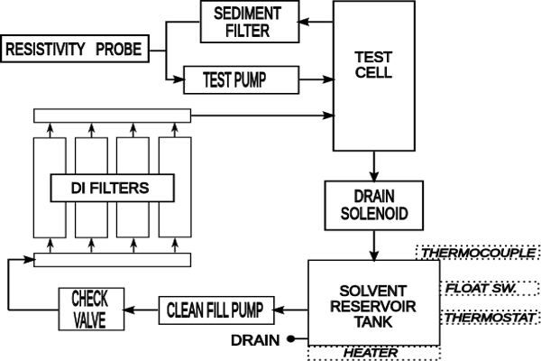
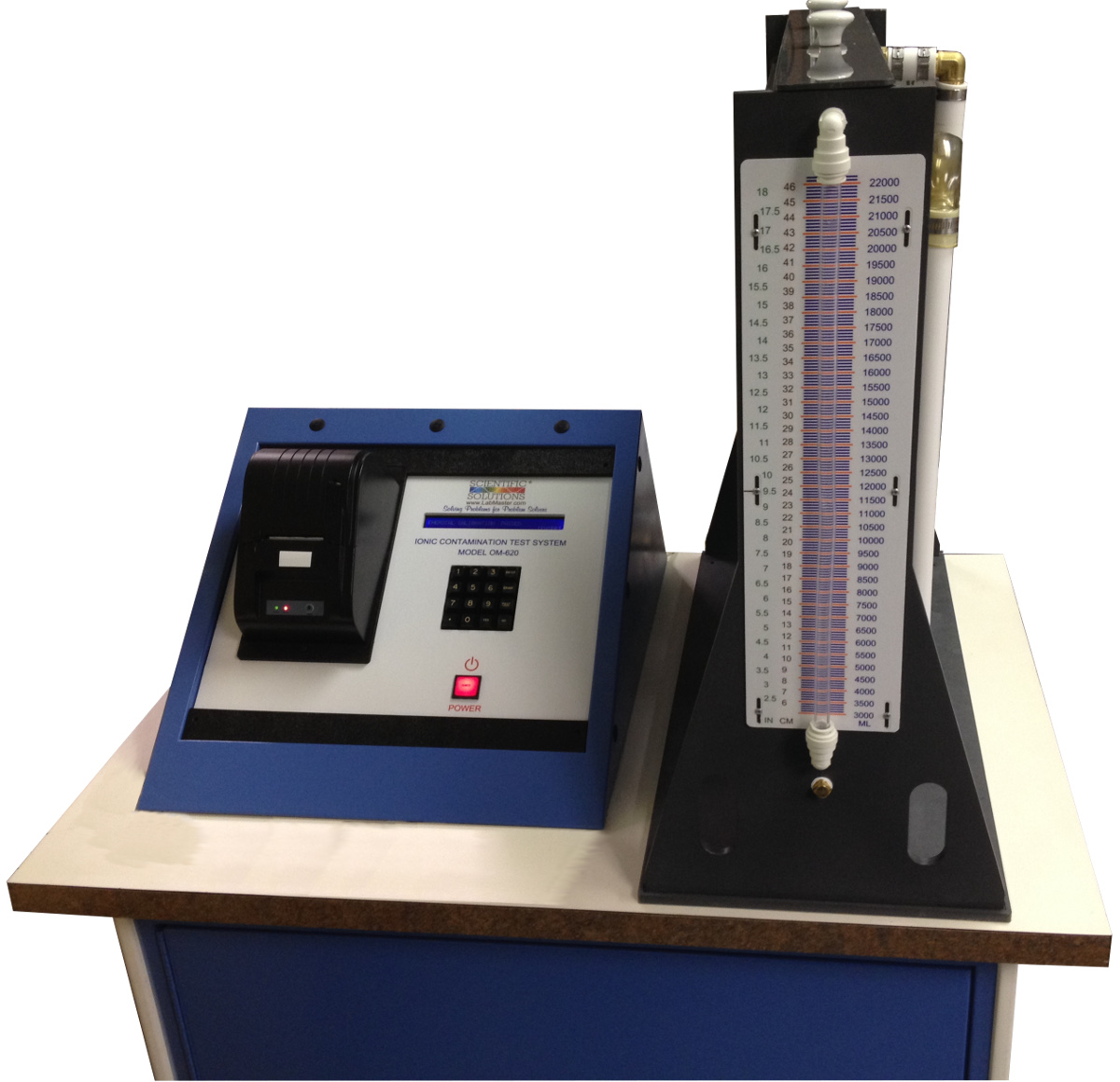
- An automated Resistivity of Solvent Extract (ROSE) tester
- Conductivity dip probe with appropriate meter with temperature compensation
- Hydrometer (0.800 – 0.900) for ROSE tester calibration
- Thermometer for ROSE tester calibration
- Clean room (non-ionic) gloves or forceps
- KAPAKTM plastic bags or equivalents (see 6.9)
- Bag sealing equipment
- Water bath, capable of sustaining an 80°C ± 2°C [176°F ±3.6°F] temperature
- Second water bath capable of sustaining a 25°C ± 1°C [77°F ± 1.8°F] temperature
- Precision solvent measurement equipment, such as class A pipettes
- Volumetric glassware
- Plastic ware – high density polyethylene, polymethylpentene (polypentene) or equivalent.
- Extract solution: 25% v/v deionized water (18 MΩ-cm nominal resistivity), 75% v/v 2-propanol (electronic or HPLC grade). No alternative solution or composition is allowed.
- Sodium Chloride – reagent grade
- Analytical balance accurate to 0.001 grams
5 Procedure
5.1 Extraction
NOTE: Throughout this procedure, do not touch the sample boards with bare hands. Use the clean room gloves specified or use clean forceps.
5.1.1 Calculate the surface area of the PWB using:
Area (in cm 2 ) = Length x Width x 2
5.1.2 Prepare a volume of extract solution specified in 4.
5.1.3 Using clean room gloves or clean forceps, place the PWB into virgin KAPAKTM bags. Choose the bag size to give at least an additional 2.5 cm [1.0 in] on each side of the board
to minimize the amount of extract solution used. Allow at least an additional 5 cm [2.0 in] above the board top.
5.1.4 Using a pipette or graduated cylinder, add a volume of the extract solution into the bag. The amount will depend on the area of the board surface. This usually varies from 0.8 mL/cm 2 [5.2 mL/in 2 ] up to about 3 mL/cm 2 [19 mL/in 2 ]. For example, a 10 cm x 11.5 cm [3.94 in x 4.53 in] board would require about 100 mL of solution. The amount of solution should just cover the board completely when most of the air is forced out of the bag.
5.1.5 Force most of the air from the bag and heat seal the bag. This involves contact with a hot metal bar. Take reasonable precautions to keep extract solution from contacting the hot bar. Alternatively, the top of the bag may be folded over and clipped shut.
5.1.6 Place the bag(s) vertically in a water bath which has stabilized at 80°C [176°F]. Make sure that the boards do not float above the water line. Do not allow the water from the bath to enter the bag or for extract solution to leak out of the bag.
5.1.7 Allow the boards to extract in this manner for a period of time of 60 ± 5 minutes.
5.1.8 Following the extraction of 5.1.7, remove the bags from the water bath and allow the extract solution to cool for at least 30 minutes, with the specimen still in the bag.
5.1.9 Using clean tongs or forceps, remove the PWB from the bag.
5.2 Measurement – DIP Probe Method
5.2.1 Calibration of Bridge. This is essential in this method because there can be no correlation between resistivity/conductivity readings and NaCl equivalents without calibration.
5.2.1.1 Prepare a standard NaCl solution from a weight of dry reagent grade NaCl salt dissolved in deionized water to produce a final diluted concentration of 0.06 g/liter NaCl (5 mL
equals 300 μg NaCl).
5.2.1.2 Place 1 liter of the 2-propanol water solution (at the calibration temperature of the bridge in use) in a plastic beaker.
NOTE: The 75 % v/v 2-propanol solution must be used in this calibration. Water cannot be used since it is not the test solution used in the procedure. The test solution used in this calibration can be recleaned by passing through the DI column until the required resistivity/conductivity is obtained.
5.2.1.3 From a 50 mL burette, add to the liter of test solution, 5 mL of the standard 0.06 g/liter NaCl solution. Stir and measure resistivity/conductivity.
5.2.1.4 From a 50 mL burette, add to the liter of test solution, 20 additional mL of the standard 0.06 g/liter NaCl solution, for a total of 25 mL. Stir and measure resistivity/conductivity.
5.2.1.5 From a 50 mL burette, add to the liter of test solution, 25 additional mL of the standard 0.06 g/liter NaCl solution, for a total of 50 mL. Stir and measure resistivity/conductivity.
5.2.1.6 Plot a three point nomogram of Conductivity vs. Solution Concentration (in μg/liter NaCl). See Figure 1 for example. You should get a linear relationship. Use a best fit line obtained with a piecewise linear method.
Figure 1 Nomogram of Conductivity vs. Solution Concentration
5.2.2 Test Procedure – DIP Probe
NOTE: If desired, this test can be run at other temperatures; however, the calibration process must be repeated for the alternative temperature. This calibration process need only be done once, providing the conductivity cell has not been exposed to harsh chemicals which would alter the cell constants. If the conductivity cell is routinely used on harsh chemical solutions (e.g., plating baths), then the calibration should be repeated before every test run.
5.2.2.1 Place the KapakTM bags containing the extract solutions into the 25°C [77°F] water bath and allow the extract solutions to reach 25°C [77°F].
5.2.2.2 Insert the conductivity probe into the KapakTM bag containing the room-temperature extract solution. It is important that the extract solution be measured at the same temperature used for the calibration solutions. Immerse the probe to a suitable depth.
NOTE: A ‘‘suitable depth’’ is one which covers the cell electrodes, but not an immersion which covers the wiring. Many cells are marked with a scribed line which indicates the proper immersion depth.
5.2.2.3 Gently agitate the solution. Read the conductivity of the solution. The time between immersion of the cell and taking the reading should be the same as used for the calibration
curve. Sufficient time should be allowed for the reading to come to equilibrium (no change for two minutes).
NOTE: Between measurements, rinse the cell with deionized water and leave the cell soaking in virgin extract solution. Never use a dry cell as this is bad technique.
5.2.2.4 Using the linear relationship formed in 5.2.1.6, determine the concentration of sodium chloride corresponding to the conductivity reading. Use the equation given below to determine the total micrograms of sodium chloride equivalence per square centimeter (μg NaCl Eq. /cm 2 )
Using the nomogram:
Conductivity of Unknown →
Concentration of Unknown
Concentration
(μg/liter)
x
5.2.2.5 If the conductivity of the unknown solution is outside of the bounds represented on the existing nomogram, then continue the technique used to generate the nomogram (see 5.2.1) until the bounds contain the conductivity of the unknown solution.
5.3 Measurement – Static ROSE Tester Method
NOTE: This section was developed using an Omegameter 600SMD with a 10,000 mL cell. Make appropriate changes to the procedure to accommodate other static ROSE testers.
5.3.1Perform a system verification check.
5.3.2 Set the instrument to an appropriate amount of solvent volume. A target solution level should be 1.5 mL for one cm 2 of board surface. It is not necessary to cover the spray jets (if applicable). If the lid is on the test cell, the CO 2 mixing is minimized.
5.3.3 Enter the appropriate surface area into the instrument.
5.3.4 To allow for the volume of solvent that is to be added, the instrument setup volume will be set at the minimum volume (e.g., 2300 mL) plus the volume of solution in the extraction bag (e.g., 100 mL).
Dwell time or run time: 2 minutes
Pass / Fail Value: None
Begin the test and follow the test prompts.
Remove the cell cover.
5.3.5 Carefully open the test bag and quickly pour the extract solution into the test cell. To minimize CO 2 absorption, the addition should be made as quickly as possible and the cell cover quickly replaced.
5.3.6 The instrument should very quickly reach equilibrium (10 – 15 seconds) and then should remain essentially unchanged for the remainder of the two minute run.
5.3.7 Log the reading in total μg of sodium chloride equivalence per cm 2 .
5.3.8 Static ROSE Calculation Example:
Testing a bare board, 10 cm x 20 cm [3.9 in x 7.9 in]
Surface area is 10 cm x 20 cm x 2 = 400 cm 2 [62 in 2 ]
Bag size should be about 15 cm x 30 cm [5.9 in x 12 in] or larger
Extract solution would be about 620 mL
ROSE volume input to 4620 mL (4000 mL to cover sprays and 620 mL from extraction)
ROSE tester cell volume set to 4000 mL.
Run time – 2 minutes
5.4 Measurement – Dynamic ROSE Tester Method
5.4.1 Perform a system verification check.
5.4.2 Program the instrument with the appropriate surface area of the board.
5.4.3 Cycle the instrument to the beginning cleanliness
point.
5.4.4 Carefully open the test bag and quickly pour the extract solution into the test cell. To minimize CO 2 absorption, the addition should be made as quickly as possible and the
cell cover quickly replaced.
5.4.5 When the instrument completes the test, log the reading in total μg of sodium chloride equivalence per cm 2 .
6 Notes
6.1 The background for this test method may be found in technical papers:
‘‘Rationale and Methodology for a Modified Resistivity of Solvent Extract Test Method,’’ Philip W. Wittmer, IPC 1995 Fall.
‘‘Ionic Cleanliness of LPISM Circuit Boards,’’ Hank Sanftleben, IPC 1995 Fall Meeting Proceedings, S13-3.
6.2 PC-HDBK-001 ‘‘Handbook and Guide to the Requirements for Soldered Electrical and Electronic Assemblies to Supplement ANSI/J-STD-001’’ is another source for understanding ROSE testing in general.
6.3 This method may also be known as the modified-ROSE test. This test, due to its longer extraction time and higher extraction temperature, has demonstrated better correlation
with the total ion determination by ion chromatography than IPC-TM-650, Test Method 2.3.25, Detection and Measurement of Ionizable Surface Contaminants by Resistivity of Solvent Extract (ROSE) Method. However, as a bulk contamination measurement method, it cannot distinguish individual ion species.
6.4 From an analytical standpoint, the dip probe method is preferred as more repeatable than the automated ROSE testers and avoids many of the test inaccuracies (e.g., CO 2 absorption from spray agitation) inherent in those instruments. It should be stressed that the dip probe method is an electrolytic conductivity measurement and must be temperature-compensated.
6.5 The dip probe calibrations can be run at multiple temperatures and a family of curves generated, widening the test window for use with this method. Higher temperatures, however, will lead to a faster 2-propanol evaporation rate. The test can also be run with more dilute concentrations, prepared by series dilution.
6.6 Conductivity cells have a ‘‘constant’’ value. Measured readings must be multiplied by this constant. Exposure to harsh chemicals may alter the constant, making a re-calibration necessary. Do not allow the probe used for this procedure to contact sticky, oily, or resinous liquids (e.g., flux).
6.7 This procedure is intended to be a process control aid and as such, no pass-fail criteria is stated. It is expected that the fabricator/assembler will determine, with their customer, the necessary pass-fail criteria for their product by this method.
6.8 This method is best suited for monitoring and control of a previously optimized process and should not be used to generate acceptance data unless part of a larger correlation study. Values generated with this method should be correlated to acceptable electrical performance if used for acceptance.
6.9 The bag must have the following characteistics:
- No extractable ionic material in 75% 2-propanol / 25% DI water at 80°C [176°F] for 60 minutes
- 0.01 cm [0.0039 in] wall thickness minimum
- Heat sealable or mechanical seal
6.10 There is some concern regarding ROSE tester cell size. Testing a 2 cm x 2 cm [0.79 in x 0.79 in] board in a 20,000 mL cell causes such a severe dilution as to cause the signal to be lost in the noise. A recommended cell size is 5000 mL or less. Smaller cell volumes will allow for a more measurable result. If a smaller cell, or running with a smaller test volume, are not an option, then the number of bare boards can be increased, all extracted separately, and the extract solutions all tested at once
6.11 When testing hybrids or microelectronics, be aware that 2-propanol stored in glass containers can leach out materials such as sodium, borates, and silica. 2-propanol stored in plastic containers does not have such a leaching problem.
DISCLAIMER: Material in this Test Methods Manual was voluntarily established by Technical Committees of IPC. This material is advisory only and its use or adaptation is entirely voluntary. IPC disclaims all liability of any kind as to the use, application, or adaptation of this material. Users are also wholly responsible for protecting themselves against all claims or liabilities for patent infringement. Equipment referenced is for the convenience of the user and does not imply endorsement by IPC.